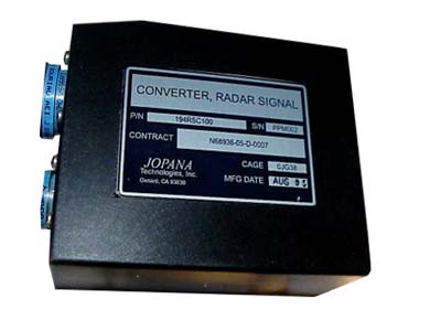
CV-4416/APN-194(V) Signal Data Converter (SDC)
Jopana Technologies’ CV-4416/APN-194(V) Signal Data
Converter (SDC) provides an inexpensive, yet reliable, method
to digitize the altitude output of the AN/APN-194(V) Radar
Altimeter Set for availability on a MIL-STD-1553B bus. The
SDC passively monitors the APN-194 analog output signal to
the cockpit Height Indicator, converting the voltage to an
appropriate digital value and providing the value to the Mission
Computer as a 1553 Remote Terminal (RT). The SDC also
monitors and converts the APN-194’s Altitude Rate signal, and
when used in conjunction with RT-1015A version of the APN-
194, it can provide the digital serial Altitude value to the 1553
interface.
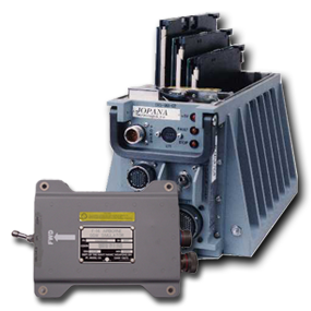
The SDC is conveniently small and
lightweight, with size dimensions of
6”x 4”x 2.25” inches and weighing just
under two pounds. Power for the SDC
is 115 VAC, 400 Hz, which is the same
as the AN/APN-194(V) RT, so special
power conversion is not necessary.
For laboratory testing, calibration, or
field service updates, it can also use
115 VAC, 60 Hz wall power,
eliminating the need for any special
power supplies or generators. It is
flight-qualified, having passed
environmental and EMI testing for
aircraft and carrier deck operations.
The SDC’s microcontroller-based design makes use of integrated peripherals to interface with external signals,
reducing component count and complexity. The TI MSP430 microcontroller integrates Flash Memory, RAM, A/D
Converter, Watchdog Timer, Serial Interfaces, and Timer units, allowing for tremendous flexibility in adjusting the
SDC’s operation via software. To allow for easy in-field software updates, the SDC also contains a USB interface
for downloading and/or calibration from just about any PC.
The SDC updates the AN/APN-194(V) analog Altitude (and Altitude Rate) value for 1553 access at 20 Hz rate,
although faster and/or slower rates can be easily implemented. The analog signals are actually sampled at a 640 Hz
rate, with the input values being averaged between output updates to reduce any noise on the input signals. The
Altitude measurement LSB is approx. 6 millivolts, which translates to approximately 0.3 ft for altitudes under 400 ft.
and approximately 2.5 ft. for altitudes above 400 ft. As part of the processing, the validity of the measured signals is
checked to make sure they are within a reasonable voltage range. Altitude and Rate validity indication bits based on
these measurements, as well as monitoring the AN/APN-194’s Altitude Validity discrete signal, are provided on the
1553 interface. The SDC also monitors the Built-In Test (BIT) indication from the Height Indicator to verify the
APN-194 responds appropriately to the BIT initiation and reports accordingly via 1553 to the Mission Computer.
When the SDC is connected to a RT-1015A/APN-194 version (i.e., with the serial digital output) and is commanded
via an external signal, the serial digital Altitude is used as the primary altitude source for responding on the 1553
bus. The analog signal for the Altitude continues to be monitored and converted as when connected with the analog
APN-194, but is stored in the a spare location of the 1553 message. The serial value is retrieved from the APN-194
at a 20 Hz rate and is updated in the same manner as the analog signals.
The SDC contains a fully-compliant, dual-redundant MIL-STD-1553B Remote Terminal interface, and is capable of
handling the entire 1553 command set. The SDC provides data to the Mission Computer by responding to a RT-to-BC
message command on the MIL-STD-1553B bus at S/A 10 of the desired RT address. The RT address for the SDC
unit is hardwired in the input connector during unit installation by jumpering the appropriate RT address lines to
ground (for a ‘low’), while ‘high’ RT address lines are left unconnected.